Convective Schemes Analysis for Scalar Transport Problems
For numerical analysis, one deals with partial differential equations. These equations are solved in time and space. Performing numerical simulations by using OpenFOAM®, one has to choose a discretization scheme for each partial differential term from a large list of numerical schemes. However, each discretization method has its numerical behavior. Thus, depending on the scheme in use, higher accuracy in terms of quantity representation (physically more correct) or numerical stability can be achieved. The following scheme analyzer allows one to investigate a wide range of different numerical schemes. The analysis is based on a simple convection equation. Tobias tried to make the analyzer flexible so that people can compare different meshes, schemes, and also OpenFOAM versions.
Tobias investigated into new scripting languages to develop the below-presented analyzer
The numerical schemes were analyzed using a simple convection equation. The equation, its derivation, and the conditions and the numerical meshes, are presented below. Previously, Tobias also added 2D slices for each numerical scheme, which is not added right now. This feature might come in the future if the community thinks it is worth extending the analyzer concerning this topic.
Equation and Conditions
Referred to literature R. Schwarze, a comparison and analysis of different numerical schemes were performed and can be investigated with the analyzer given above. A convective flow field in a defined domain (see picture 1.1) will be set-up, and the value of the scalar Φ is analyzed. The equation which is solved is an ordinary conserved transport equation including the time derivation, convective, diffusion, and source term. Since the investigation focuses on numerical schemes, the equation is going to be simplified. The general conservation equation is given by:
while the quantities represent the general ones in computational fluid dynamics. Further information can be taken from the book »Mathematics, Numerics, Derivations and OpenFOAM®«. The following definitions and assumptions are applied to simplify the equation:
- Diffusion coefficient D = 0, thus, the diffusion term vanishes
- No source terms
- Incompressible fluid and, therefore, no temperature-dependent density (constant)
- The system will be solved until a steady-state condition is reached, the time derivation is included
Hence, one can re-write the equation to:
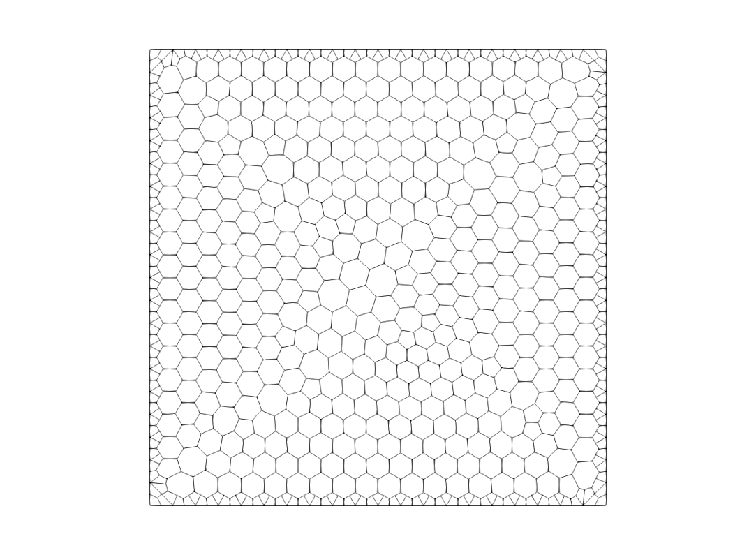
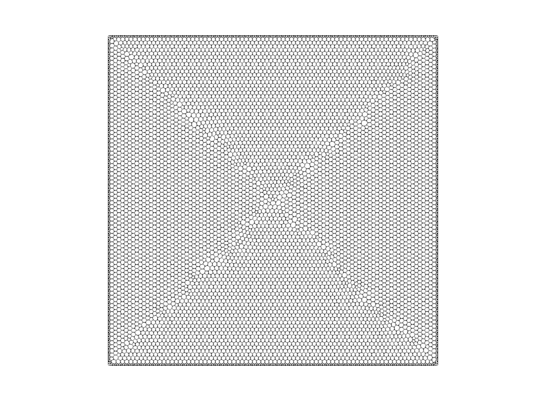
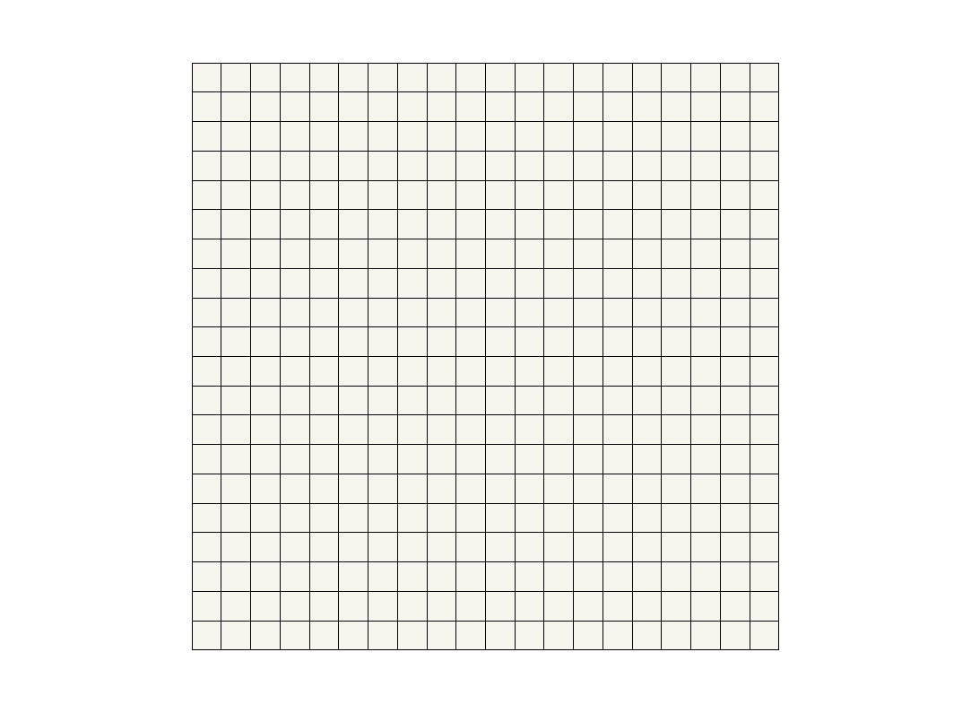
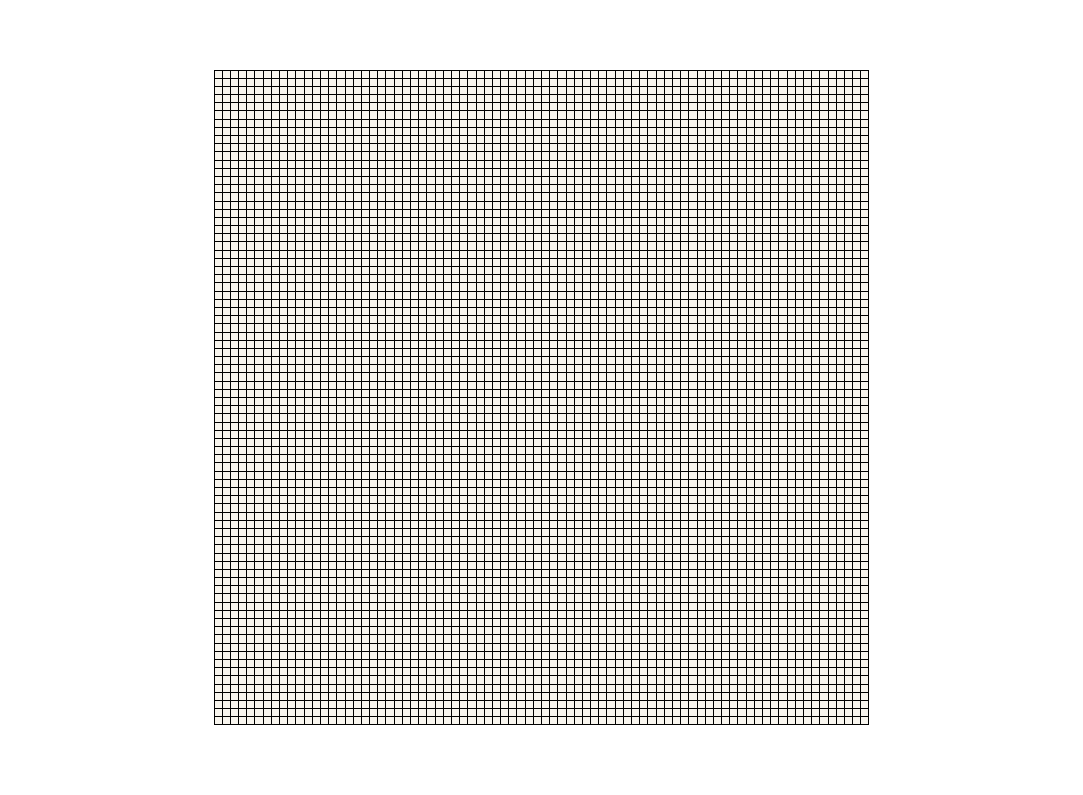
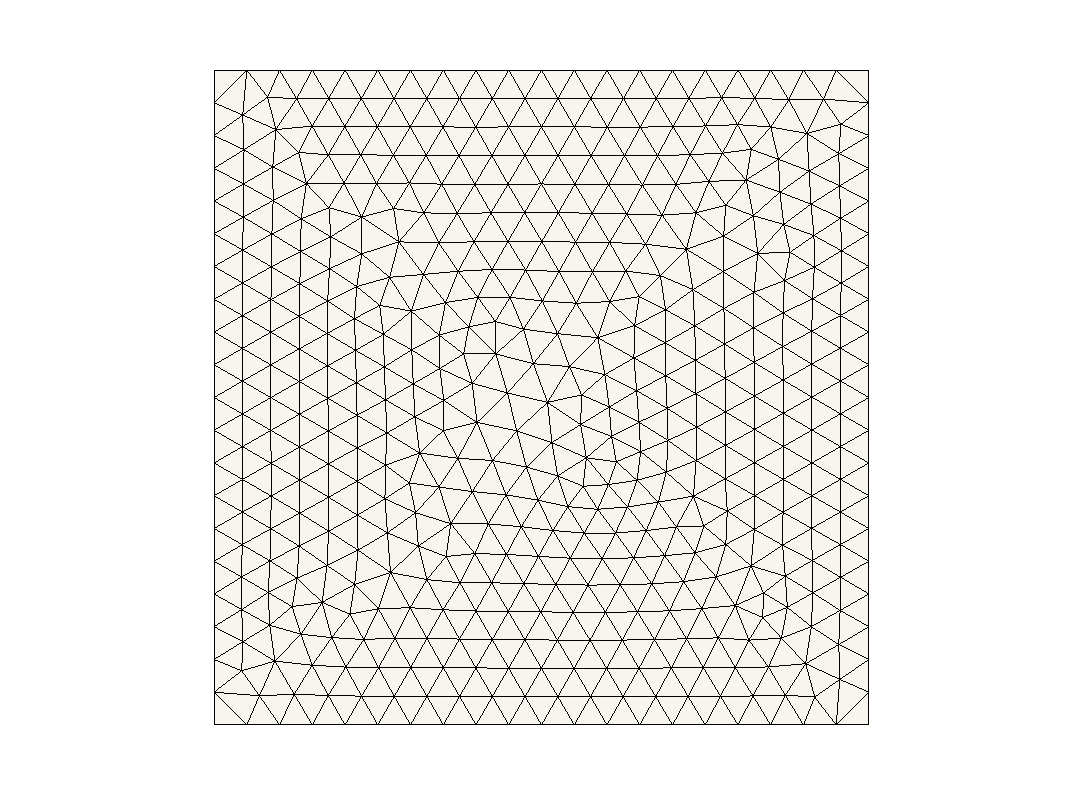
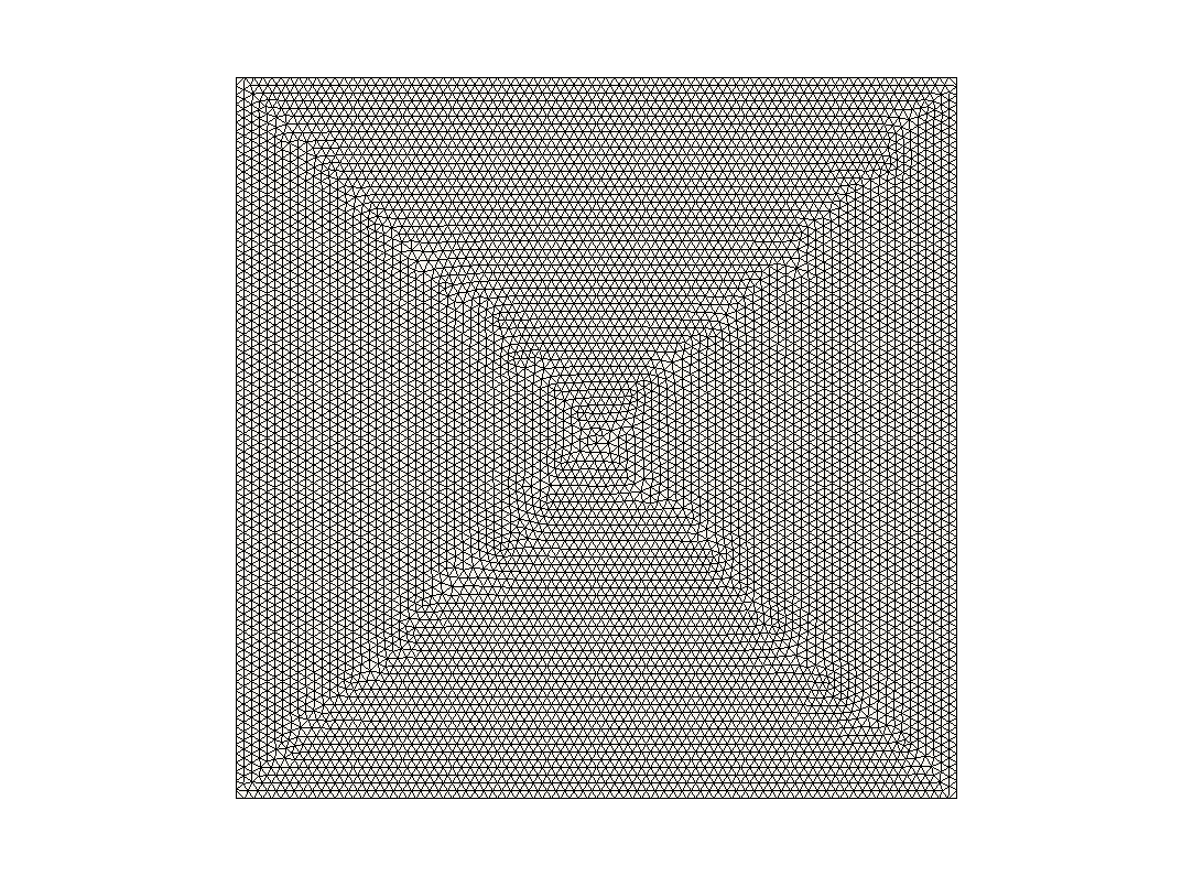
This equation is used in combination with the boundary conditions shown in the colored picture below. Without diffusion, the scalar Φ must keep a clear separation between the blue and yellow color; it should not mix as indicated by the dashed line. Using this setup, one can investigate into numerical schemes, while different phenomena can be shown, such as numerical diffusion, instability, and accuracy. Furthermore, the schemes are depended on the used numerical mesh. Hence, different meshes types were investigated as well as three different mesh-densities. Therefore, the analysis considered hexahedral, tetrahedral, and polyhedral meshes. For the hexahedral mesh, a 0° and 45° analysis was performed. The angle refers to the angle between the flow vector and the normal surface vector. The investigation was performed by using a standard OpenFOAM® solver named »scalarTransportFoam«. The mesh densities are equal to
20 x 20 cells
40 x 40 cells
80 x 80 cells
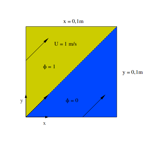
Important notice: All simulations are done with the same control settings. Hence, it can happen that some schemes will blow up due to the time derivation and numerical instability, although this scheme will produce good results if we choose a smaller time step. This behavior is related to some dimensionless numbers such as the Courant or Fourier number. These numbers always have to be in a certain »valid« range. If one goes above the validity limit, one commonly has two options to take this into consideration and allow a stable calculation: a) decreasing the time-step; b) numerical stabilization using different methods. This is the reason why one might observe different results for different schemes by using the same time-step. In other words, the analysis performed by Tobias Holzmann is consistent in the numerical set-up. However, for some schemes, this set-up does not fit the numerical needs and thus the scheme does not provide accurate results. József Nagy also discussed this phenomenon. The test case is identical to the one given below. The different meshes are further presented underneath.
Structured Mesh
Transport under 0°
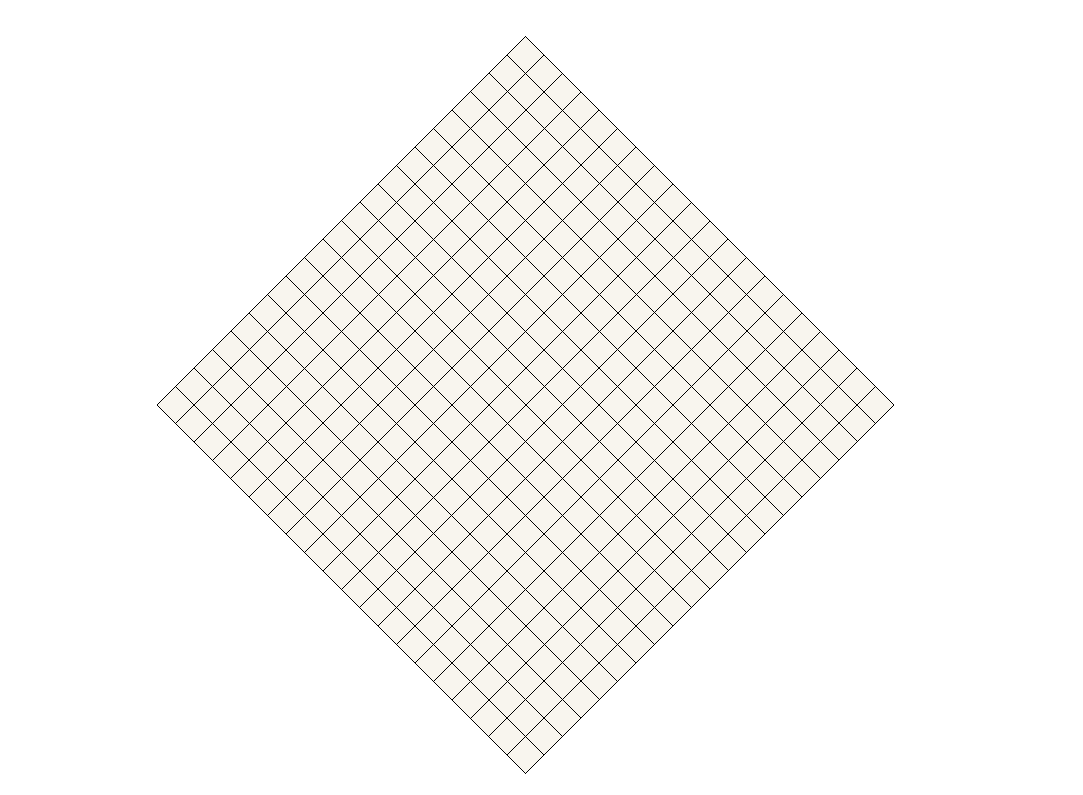

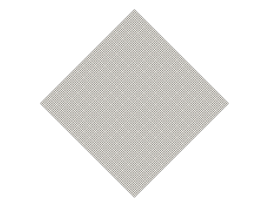
Structured Mesh
Transport under 45°

Unstructured Mesh (Tetrahedral)
Arbitrary face-angles

Structured Mesh (Polyhedral)
Arbitrary face-angles
